
Vibratory feeders designed digitally, delivered in weeks
Bowl, linear, step and drum feeding systems for assembly lines - from 3D part analysis to commissioning, with no manual welding and with repeatable geometry.

Digital-Bowl approach
Why a digitally designed bowl
Fast delivery and repeatability
The standard build cycle is 4 to 8 weeks, instead of the months needed for conventional welded bowls. The digital model allows an identical replacement bowl to be built at any time in the future.
Minimal service downtime
The digital 3D design allows a new, identical replacement bowl to be produced quickly, without waiting for a new mold to be made by hand.
High wear resistance and coatings
Coatings adapted to abrasive and oily parts extend the service life of the bowl and reduce maintenance costs.
Quieter operation
Polymer and coated bowls run quieter than conventional stainless steel designs, which matters for workstations along the line.
Precise, repeatable geometry
Eliminating manual welding errors ensures an identical path and part orientation on every bowl.
Technical support and spare parts
We keep the digital model of the bowl on file - spare parts and technical support remain available for years after commissioning.
How we work
Build process
 01
01Part analysis and lab testing
Analysis of part geometry, weight and behavior, and testing of the motion path before the bowl is built.
 02
023D design in SolidWorks
A digital model of the bowl and track adapted to the specific part geometry.
 03
033D printed bowl prototype
A polymer prototype to verify geometry and part path before the final bowl is produced.
 04
04Special coating
A coating matched to the part type - abrasive, oily or sensitive materials.
Peripherals
Additional equipment
 01
01Hoppers
Hoppers to increase autonomy and reduce downtime on the shop floor.
 02
02Enclosures and stands
Aluminum base plates or free-standing stands. Sound enclosures to reduce noise on the shop floor.
 03
03Separators and pneumatics
Part separators built with SMC/FESTO pneumatics for reliable singulation.
 04
04PLC control
Control via Siemens PLC with Harting connectors for fast servicing.
Systems
Types of vibratory feeders

Circular vibratory feeders
Orienting and feeding small parts at high speed - screws, fasteners.

Linear vibratory feeders
Guiding and synchronizing parts from the bowl feeder to the pick-up point on the line.

Step feeders
A climbing system for plastic and lightweight parts that need gentle handling.

Drum feeders
A rotary system for feeding springs and coiled parts.

Conveyors
Conveyor belts for linking stations and synchronizing material flow on the line.
Delivered projects
References

Feeder for blister packaging

Feeding system for GFP elements

Feeding system for plastic sticks
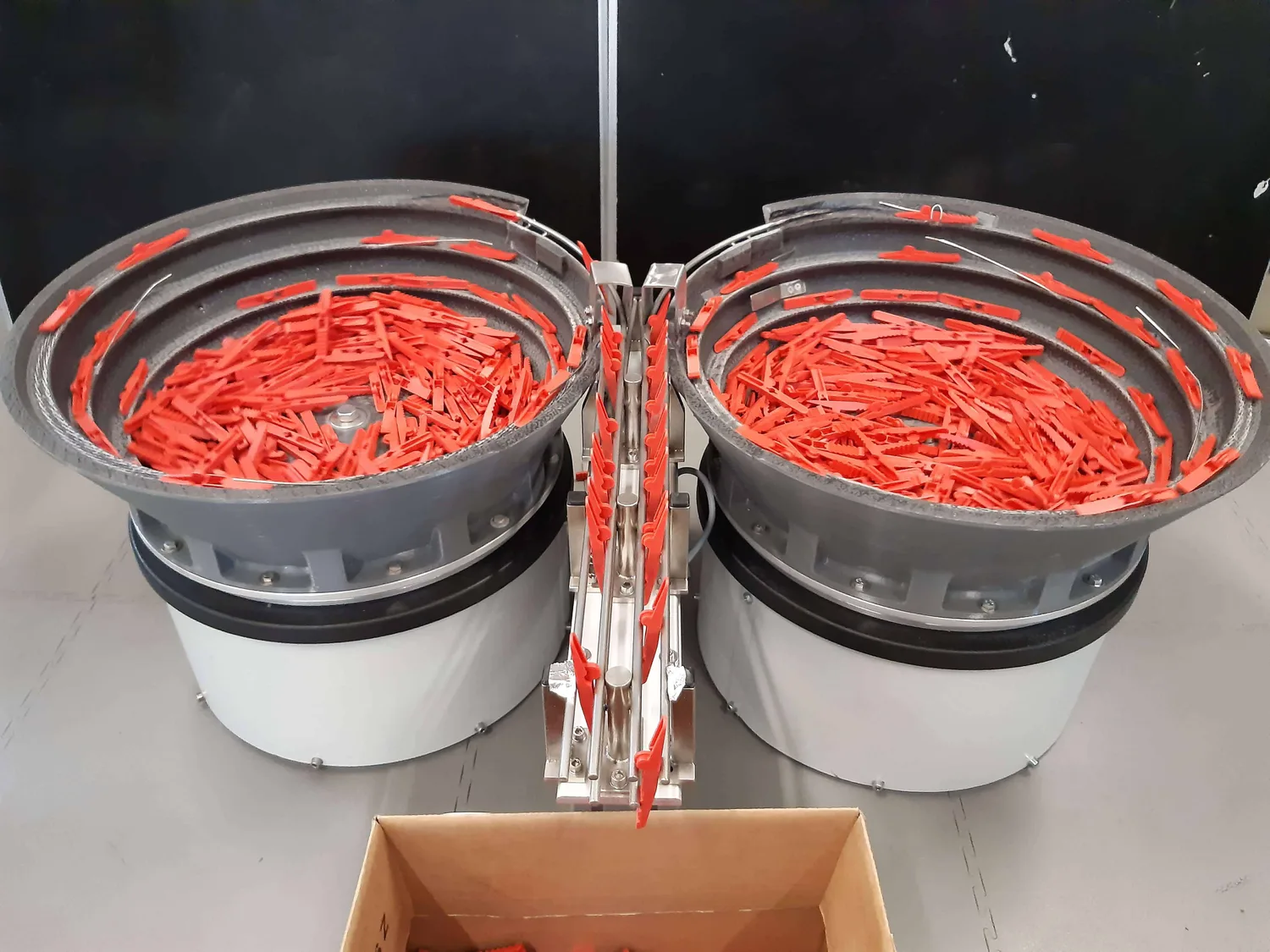
Vibratory feeding system for clothespin assembly

Vibratory feeding system for metal parts

Feeding system for metal rings
Ecosystem
Feeder drives
Working with leading global manufacturers such as Afag, RNA and Kendrion lets us install the most reliable components on the market, ensuring long service life and worldwide availability of spare parts.





Drives for bowl and linear vibratory feeders
To drive and control sorting bowls and linear tracks, we use systems from our long-standing partners Afag (Emerson) and RNA Automation.
Other drives and magnets we use
To drive hoppers, we use reliable Magnet-Schultz, IMA Magnets or Kendrion magnets controlled by Audimat TUXEL or TUMAC.
For specific requirements, we also offer pneumatically driven ATEX (EX) versions.
Questions and answers
Frequently asked questions
How long does it take to build a vibratory feeding system?
Building a standard, average vibratory feeding system consisting of a bowl feeder and a linear feeder takes 4 to 8 weeks, depending on part geometry, the required cycle time and operating conditions.
What affects the build time of a vibratory feeder?
Build time depends mostly on part geometry and the operating environment. Simple geometries such as cylinders and rings that are dry and clean do not require complex tracks in the feeder. Complex geometries that need a precisely defined orientation, and difficult environments such as oily parts, extend the build because trials take longer and special coatings have to be applied and cured.
How is feeder capacity defined?
Feeder capacity is defined by how much of the operator’s time is spent working at the machine. Feeder bowls have a volume that gives them a certain autonomy, but for optimal operation and longer autonomy an additional hopper is always installed. Depending on the operator’s workload at the machine, the feeder can be refilled every 15 minutes or 2 to 4 times per shift.
Need a feeder for a specific part?
Send us the part geometry - our engineering team will give you non-binding technical feedback.